What is Finite Element Analysis?
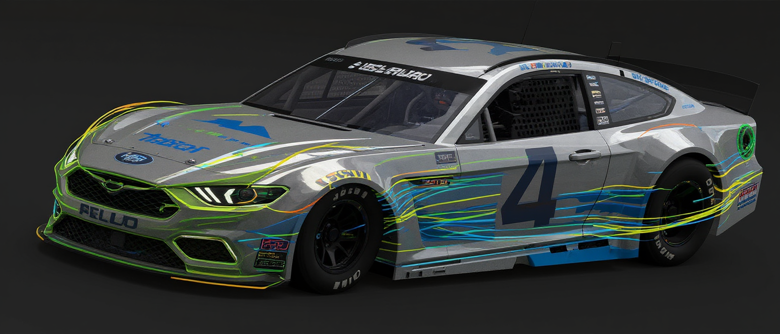
Finite Element Analysis (FEA) is a computational method that divides a complex structure into thousands of small elements, solving the governing equations of mechanics across each one. The result is a high-resolution digital picture of how stresses, strains, displacements, temperatures, and vibrations distribute through your component under any load case you define.
CHS Intl applies FEA across the full product development cycle — from early concept screening to final design validation and regulatory certification support. For companies without in-house simulation capability, outsourcing FEA eliminates the need for expensive software licences and specialist recruitment while delivering expert-level results on demand.
Our FEA Capabilities
- Linear static stress & deflection analysis
- Dynamic loading & transient response
- Nonlinear material behaviour (plasticity, hyperelasticity)
- Fatigue life prediction (S-N and ε-N approaches)
- Fracture mechanics & crack propagation
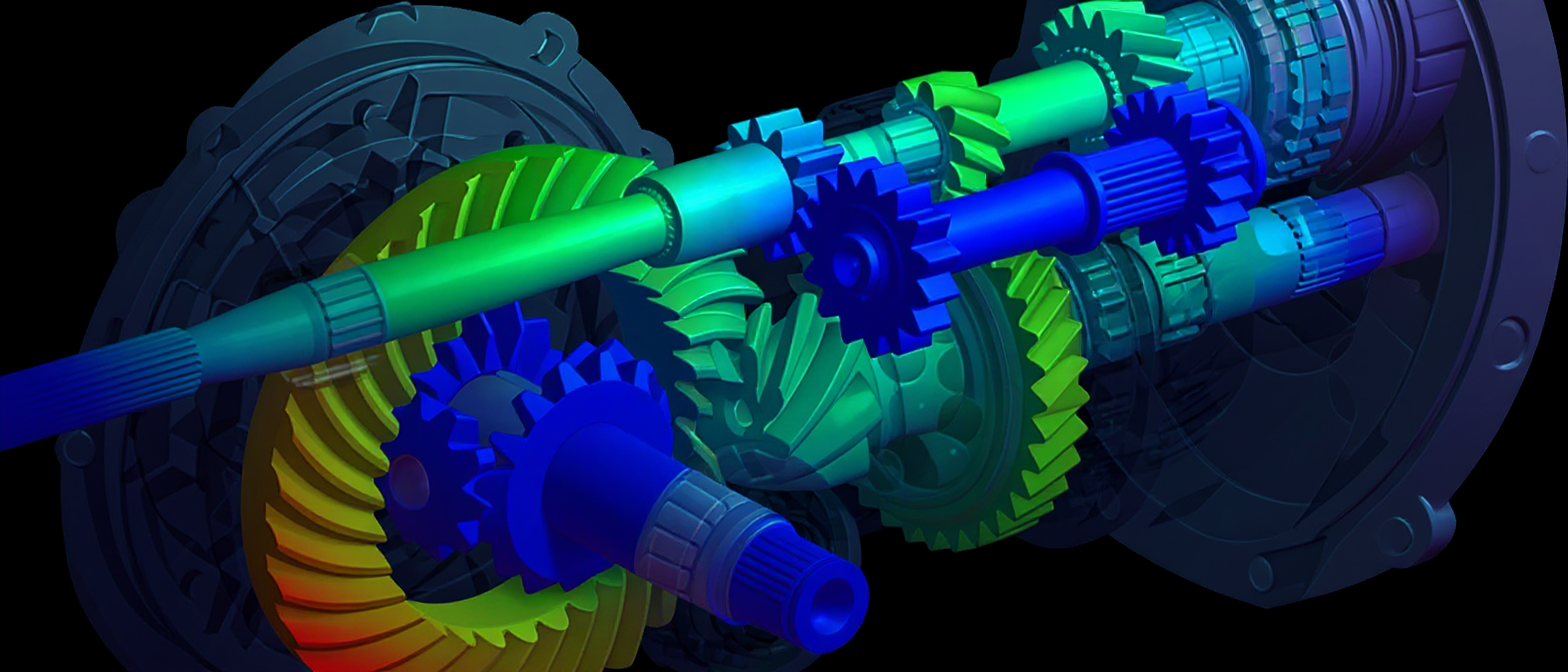
- Modal analysis & natural frequency extraction
- Harmonic & random vibration response
- Buckling and structural stability
- Contact mechanics & joint simulation
- Thermal stress & thermomechanical coupling
- Composite laminate analysis
- Weld & bolted joint assessment
Software We Use
- ANSYS Mechanical
- Abaqus / CAE
- Siemens NX Nastran
- SolidWorks Simulation
- COMSOL Multiphysics
Industry Applications
Our Analysis Process
-
Geometry & CAD Preparation — We receive your CAD model, carry out necessary simplifications, and prepare the geometry for meshing without losing load-path fidelity.
-
Mesh Generation — High-quality structured or unstructured meshes are generated with targeted refinement at stress concentrations, welds, and interfaces.
-
Material & Load Definition — Material properties, boundary conditions, contacts, and load cases are applied according to your operating requirements and applicable design codes.
-
Solver Execution — We run analyses on dedicated high-performance computing infrastructure for fast turnaround, even on large assemblies.
-
Post-Processing & Interpretation — Results are critically reviewed and presented as clear engineering reports with stress plots, safety margins, and actionable design recommendations.
-
Design Iteration Support — We remain available for follow-up runs as your design evolves, ensuring the final geometry meets all structural requirements.
Applicable Standards
- ASME VIII Div. 1 & 2
- EN 13445
- DNVGL-RP-C208
- IIW Fatigue Guidelines
- EUROCODE 3
- MIL-HDBK-5
- ASTM E1049
Example Outcome
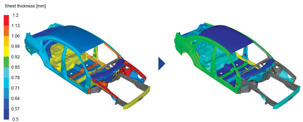
A manufacturer of unfired pressure vessels needed to reduce material cost on a range of high-pressure heat exchangers without compromising compliance with EN 13445. CHS Intl performed a Design by Analysis (DbA) study per EN 13445-3 Annex B, applying FEA stress linearisation to reclassify stresses at nozzle junctions and shell-to-head transitions. The results demonstrated that the existing design was significantly over-conservative in three locations, allowing wall thickness reductions of 12–18 mm across the main shell and nozzle necks.
18% wall thickness reduction — saving €38,000 per vessel in material and welding costsFrequently Asked Questions
What is the difference between linear and nonlinear FEA?
Linear FEA assumes that material behaviour, geometry, and boundary conditions remain constant throughout the analysis — making it fast and well-suited to elastic stress checks under moderate loads. Nonlinear FEA accounts for large deformations, plastic material behaviour (such as metal yielding), or contact conditions that change as the load is applied. CHS Intl selects the appropriate analysis type based on your load levels, material, and the accuracy required by the applicable design code.
How accurate is FEA compared to physical testing?
A well-validated FEA model typically predicts stresses and displacements within 5–10% of physical test measurements. Accuracy depends on mesh quality, the fidelity of the material model, and how precisely boundary conditions represent the real loading. At CHS Intl, all analyses include a mesh independence study and, where test data is available, a correlation step to confirm model accuracy before the final results are reported.
What file formats do you need to start an FEA project?
We work with all standard CAD formats: STEP and IGES are preferred as they are solver-neutral, but we also accept Parasolid, ACIS, SolidWorks (.sldprt/.sldasm), CATIA V5, NX, and Creo files. Alongside the geometry we need material specifications, the load cases (forces, pressures, temperatures), and the applicable design code or safety factor requirements.
Can FEA be used for design code compliance such as ASME VIII or EN 13445?
Yes — this is called Design by Analysis (DbA) and is explicitly permitted by both ASME VIII Division 2 and EN 13445-3 Annex B. DbA uses FEA stress linearisation and stress classification to demonstrate that the equipment meets the code's allowable stress limits, including primary membrane, bending, and peak stress categories. CHS Intl regularly produces DbA reports accepted by Notified Bodies for PED certification.
How long does an FEA analysis typically take?
A straightforward linear static analysis of a single component typically takes 3–5 business days from receipt of CAD to delivery of the report. Complex assemblies, nonlinear analyses, or fatigue studies involving multiple load cycles may require 7–15 business days. We always confirm the schedule at project kick-off and flag any issues as soon as they arise.
What is the benefit of outsourcing FEA rather than doing it in-house?
Running FEA in-house requires significant investment in software licences (ANSYS Mechanical alone can cost €30,000–€80,000 per year), hardware, and specialist training. Outsourcing to CHS Intl gives you on-demand access to a full suite of solvers, experienced analysts, and HPC computing — with no overhead between projects. It is particularly cost-effective for companies that need occasional analyses rather than a continuous simulation workload.