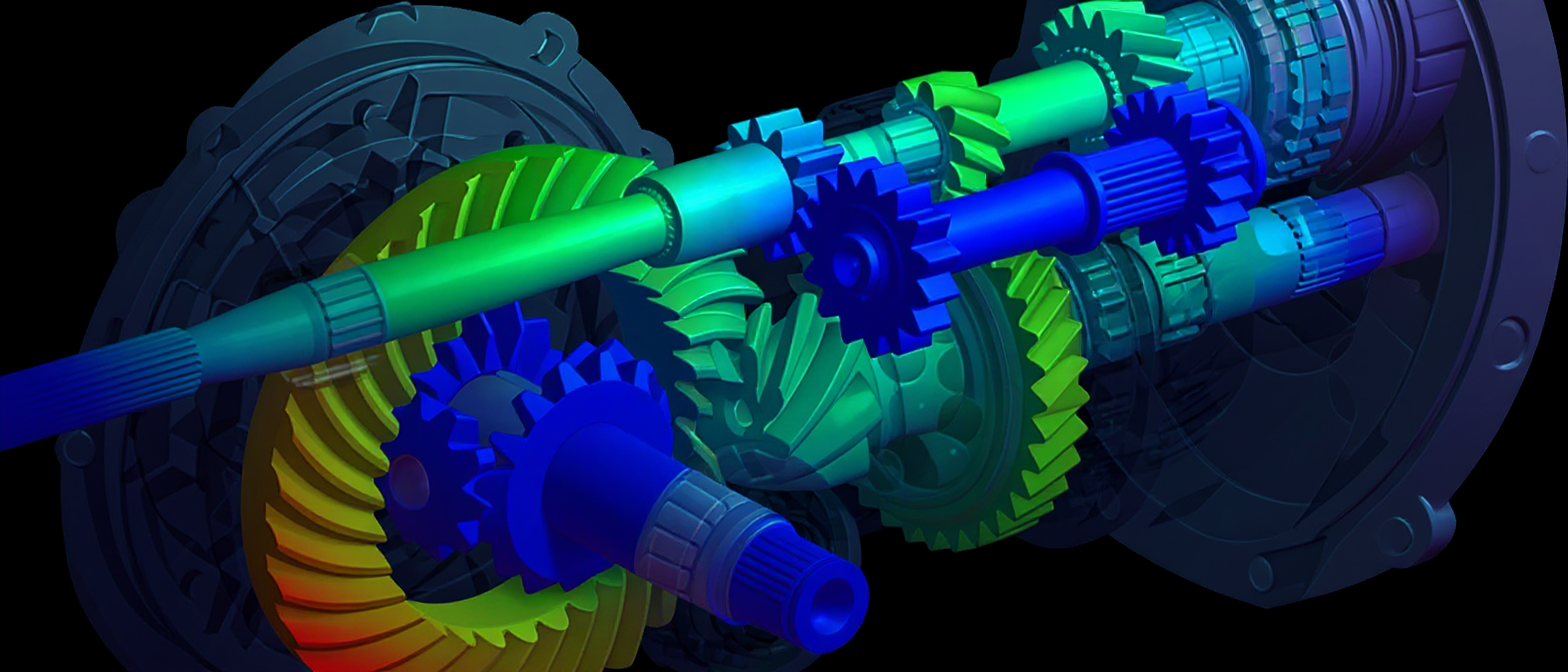
Acoustic & NVH Simulation
Noise, Vibration, and Harshness (NVH) performance is increasingly a critical differentiator across industries — from passenger vehicle comfort to industrial machinery noise regulations and consumer electronics quality perception. Virtual acoustic simulation allows engineers to predict and optimise sound behaviour long before physical prototypes exist.
CHS Intl combines structural FEA, CFD, and acoustic solver expertise to deliver coupled vibro-acoustic and aero-acoustic analyses tailored to your product and regulatory context. Addressing NVH problems late in development — after physical prototypes have been built — is typically 10 to 100 times more expensive than resolving them at the simulation stage. Early acoustic simulation is therefore not just a technical tool, but a direct cost control measure.
Our Acoustics & NVH Capabilities
- Modal analysis & natural frequency extraction
- Harmonic & random vibration response
- Structural-acoustic coupling (vibro-acoustics)
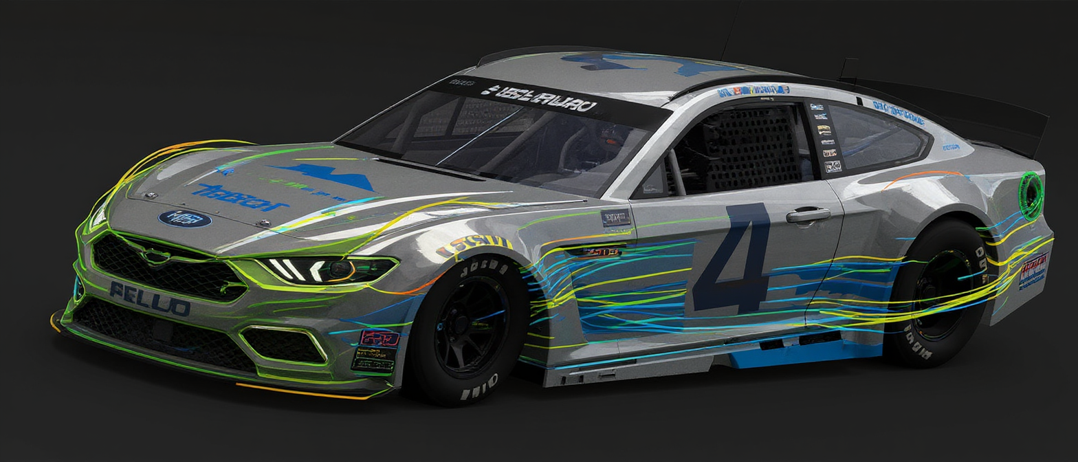
- Aero-acoustic noise prediction (CAA)
- Cavity acoustics & standing wave analysis
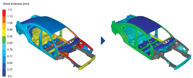
- Sound transmission loss (STL) modelling
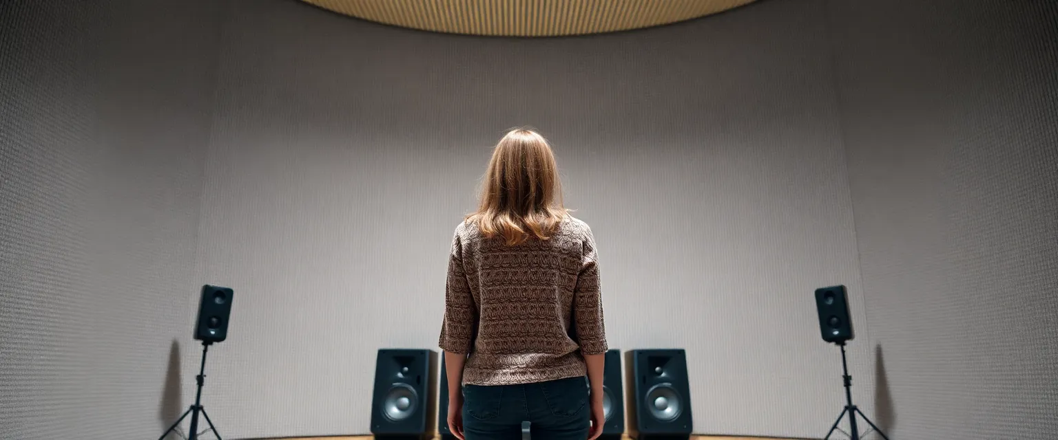
- Sound absorption coefficient characterisation
- Insertion loss of acoustic treatments
- FEM and BEM acoustic solvers
- Statistical Energy Analysis (SEA) for high frequency
- Transfer Path Analysis (TPA)
- Psychoacoustic metrics (loudness, roughness, sharpness)
Software We Use
- ANSYS Mechanical
- COMSOL Acoustics
- LMS Virtual.Lab Acoustics
- Actran
- ANSYS Fluent (aero-acoustics)
Industry Applications
Our Analysis Process
-
Problem Definition — We establish the frequency range of interest, critical noise sources, receiver locations, and applicable noise limits or targets.
-
Structural Model Setup — A validated FEA model provides the vibrating surface velocities that drive the acoustic model (for vibro-acoustics) or the modal basis for SEA.
-
Acoustic Domain Mesh — Fluid acoustic meshes are generated for FEM approaches, or boundary element meshes for BEM — with element size governed by the maximum frequency of interest.
-
Source & Boundary Conditions — Excitation forces, acoustic sources, absorbing boundaries (PML or impedance), and material absorption data are applied.
-
Frequency or Time Domain Solve — Harmonic (frequency sweep), transient, or eigenvalue solutions are computed and verified for convergence.
-
Post-Processing & Reporting — Sound pressure levels, sound power, directivity patterns, and psychoacoustic indicators are extracted and presented with design recommendations.
Example Outcome
A manufacturer of reciprocating compressors for natural gas applications was failing the EU Machinery Directive declared sound power level limit of 105 dB(A) at product launch. Physical testing confirmed the unit measured 111 dB(A). With no time for a full redesign, CHS Intl built a vibro-acoustic FEM model in COMSOL Acoustics, coupling the structural modes of the crankcase and cylinder head to an exterior acoustic radiation model. The analysis identified that two cover panels were responding resonantly at the fundamental firing frequency of 47 Hz, dominating the radiated sound power. Constrained-layer damping treatment was applied to both panels and a stiffening rib was added to one cover. A confirmatory re-analysis predicted 107.5 dB(A).
3.5 dB(A) reduction in 2 weeks — Machinery Directive declaration achieved without physical redesignFrequently Asked Questions
What is the difference between NVH and acoustics simulation?
Acoustics simulation focuses on sound — how pressure waves propagate through air or fluid, are absorbed by materials, and are perceived by a listener. NVH (Noise, Vibration, Harshness) is a broader discipline that includes the structural vibration sources that generate sound, the transmission paths through which vibration travels, and the acoustic response at the receiver. In practice, NVH simulation couples structural FEA (for vibration) with acoustic solvers (for sound radiation), which is exactly the vibro-acoustic workflow CHS Intl deploys.
What frequency range can acoustic simulation cover?
The practical frequency range depends on the method used. Finite Element Method (FEM) acoustics is most efficient below approximately 1–2 kHz, where the number of elements remains manageable. Boundary Element Method (BEM) is effective in the same range for exterior radiation problems. For high frequencies (above 1–2 kHz), Statistical Energy Analysis (SEA) is preferred as it becomes computationally more efficient than FEM. CHS Intl selects the appropriate method — or combines them in a hybrid approach — based on your target frequency range.
What is aero-acoustics and when is it relevant?
Aero-acoustics (or Computational Aero-Acoustics, CAA) studies noise generated by turbulent flow — for example, wind noise around a vehicle mirror, fan blade tonal noise, or flow-induced resonance in a pipe. It requires a high-fidelity CFD simulation (typically LES or DES) to resolve the turbulent flow structures that act as sound sources, which are then propagated using an acoustic solver. It is particularly relevant for automotive wind noise, HVAC system noise, and industrial fan and compressor design.
How is sound transmission loss (STL) measured or simulated?
Sound transmission loss quantifies how much sound a partition (wall, panel, or enclosure) attenuates as it passes through. In simulation, this is modelled using a coupled FEM structural-acoustic model: a diffuse acoustic field excites one side of the panel, and the radiated sound power on the other side is computed. The difference in sound power levels gives the STL in dB. CHS Intl uses this approach to optimise acoustic enclosures, vehicle body panels, and industrial noise barriers before any physical prototype is made.
What data do you need to start an acoustics simulation project?
For structural-acoustic (vibro-acoustic) analysis we need: the CAD geometry, structural material properties (Young’s modulus, density, damping), excitation data (forces or accelerations as a function of frequency), and your noise target (SPL or sound power level in dB). For material characterisation (absorption coefficient, STL), we need sample dimensions and, if available, any existing test data for correlation. We are happy to scope a project without complete data upfront and identify what measurements are needed.
Can acoustic simulation help meet EU Machinery Directive noise requirements?
Yes. The EU Machinery Directive (2006/42/EC) requires manufacturers to declare the A-weighted sound power level (LWA) and, where it exceeds 80 dB(A), the uncertainty. Simulation can predict LWA during the design phase, allowing engineers to redesign to meet the limit before building a prototype. CHS Intl delivers LWA predictions with documented uncertainty estimates compatible with the EN ISO 3744/3746 measurement standards referenced in the directive.